Thermistor Probe Construction

 This page is meant to be a guide for building your own thermistor probes. These probes are simply thermistors attached to a cable that have been imbedded in epoxy inside a tube but there are a few tips and tricks here that will hopefully save you some time an mental distress. The first step is to purchase all the materials you will need. Here is an Excel file with most of the materials you will need. As with many projects like this making many probes at the same time can be faster than making them individually. I would suggest doing each step for all the probes you will be making at the same time. Now the assembly can begin...
You can click on the photos for larger images and to access all the images on this page as a slideshow. There are also some links at the bottom of the page to other helpful documents.
Nylon Strip Prep.
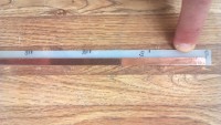
- Cut all the flexible nylon strip to length leaving it a few cm longer than you intended probe length. You will also want to get the nylon strips to lay flat and a good way to do this is to carefully use a heat gun to warm up the strips until they lay flat.
- Mark the location of all the thermistors you will install on the nylon strip. The top of the strip should be zero and this gives you a good reference point during final assembly. This is also a good time to stick the copper tape down one side of the nylon strip. The copper tape has sharp edges so you might want to wear gloves.
- Now you need to drill a small hole at each of the thermistor locations on the nylon strip. This hole is for one of the thermistor legs to pass through to the other side. It’s location isn’t too critical but it should be about halfway between the edge of the strip and the edge of the copper tape.
- Now you can glue all the thermistors to the nylon strip you have prepared. I use a very small amount of quick drying super glue for this.
- Next you can solder one leg of the thermistor to the copper tape. You need to be quick here because you don’t want to melt the nylon strip. You can then trim any excess off the thermistor leg you have soldered.
- The remaining thermistor leg should be put through the hole you drilled. The important thing here is that we don’t want the legs to touch!
Here are a few more images for this step: 1, 2, 3
Surface Thermistor Construction
It is nice to have the shallowest thermistor separate from the rest of the probe. This means we will always have a surface (2cm) temperature measurement even when the probe heaves. Also, this measurement won't be affected by the mass of the probe which can influence these very shallow measurements. This same example can also be used to construct just individual thermistor probes or groups of thermistors, say for a soil pit.
- Cut a short lenght of 2 conductor cable, about 40 to 50cm long and remove the insulation from both ends.
- Cut some short lengths of aluminum tubing, about 4cm long.
- Place a short length of heat-shrink around one of the wires from the cable and then wrap and solder one of the thermistor legs to this wire.
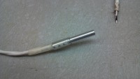
- Place another short length of heat-shrink around the other wire from the cable and solder the other leg of the thermistor it. The result should look like this and it is again important that the legs of the thermistor don't touch each other and won't come into contact with the aluminum tubing in the next step.
- Slide up and shrink the heat-shrink .
- Slide on the larger heat-shrink and the aluminum tubing so the thermistor bead is a few millimeters inside the aluminum tubing. Shrink the heat-shrink to hold everything in place.
- Fill all the aluminum tubes with epoxy, probably the same stuff you will be using for the probes. A large syringe without a needle is helpful here.
Cable Prep.
- It is now time to prep the cable that you will be using to connect the thermistors to your data-logger. The cable that I used is some heavy duty direct burial telephone cable. The nice thing about this cable is that is very tough and has a thin built-in aluminum armoring. However, the cable is also filled with a greasy gel that is a mess to deal with. There isn't any reason though that you couldn't use another kind of cable if you wished. You will just need a cable with one more conductor than the number of thermistors you will be using (i.e. one conductor for each thermistor and then one shared conductor for all the thermistors).
- When you cut your cable to length make it about 2 meters longer than you think you will need because you will need 1.5 meters for all the connections within the probe and then another half a meter for connections to the data-logger.
- Remove all the outer insulation, aluminum armoring, grease, etc. from the last 1.5 meters of the cable. There is a special chemical that can be used to remove the grease but I couldn't get any of it so I just used isopropyl alcohol and that worked fairly well with lots of paper towels. You will need to make sure to keep the pairs straight because that is the only way you can identify the individual wires visually.
- Cut all the clear tubing to length, making it about 5cm longer than your final probe length.
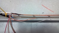
- Now with all the wires exposed you can begin connecting them to the other legs of the thermistors. I used this color code guide as my wiring scheme. You will find it is easiest to attach the cable to the top of the nylon strip so the whole thing stays together once you are done.
- Attach the two wires from your separate surface (2cm) thermistor to the common and appropriate other wire.
- As you work your way down the nylon strip trim the wires to length so that you don’t have a bunch of extra wire to stuff into the tube.
- Make sure to also attach your common wire, the two black wires in my case, to the copper tape.
- Now with all the wires attached to your thermistors you can carefully slide the whole assembly inside the clear tubing.
- Now is probably a good time to test your probe and make sure all your connections are good and the thermistors are working properly. The best way to do this is to expose the wires at the other end of the cable and then measure the resistance between the common wire (black) and each of the other wires individually. You should get a reading of about 10k ohms depending on the temperature in your work-space. Refer to the resistance to temperature conversion table if you want to double check.
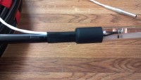
- Now you can heat shrink the cable to the top of the clear tube. You will need to also insert a very small diameter piece of tubing (mine was about 1/16 OD tubing) into the top of the probe. This small tubing is crucial during the epoxy filling step because it lets the air out and allows the epoxy to flow smoothly into the probe without trapping a lot of air bubbles.
- While you are heating the heat-shrink tubing make sure that you upper most thermistor stays the correct distance from the top of the tube. It is probably best to have a reference mark on the tube for this purpose.
Epoxy
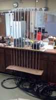 So, this really isn't an epoxy but is an unfilled urethane but it is mixed in two parts like epoxy. You should make sure to follow the instructions you receive with your order. This isn't like the epoxy you buy at the hardware store the is mixed in equal parts, for example the ratio for the stuff I used was 100:31 by volume. It is advisable to make a test batch first and then mix your production batches in amounts enough for about 5 probes. The key things that I like about this resin are: it can be ordered in clear, it has a very low glass temperature (-72°C), no shrinkage, and a low mixed viscosity.
- Assuming all your thermistors are still testing good you are ready to fill the probes with epoxy.
- You will be filling the probes from the bottom (end without a cable coming out of it) so using some cardboard make a jig to hold them up vertically. If the cardboard is over-sized it also is nice for catching most drips and small spills.
- With the probes arranged vertically insert the funnels in the ends of the tubes.
- Mix up the urethane for this batch making sure it is thoroughly mixed. I had a paint mixer that fit in a drill that worked nicely.
- Begin to pour the urethane into the funnels. It is important here that you not let the funnel become empty before adding more epoxy because doing so will allow an air bubble into the probe and cause the urethane to move very slowly.
- Keep topping off all the funnels until the probe is entirely filled. I also like to have a little extra in the funnel after the probe is filled so that any air bubbles that come out will be replaced with urethane.
- Once the probe is filled you can tie the vent tubing in a knot so that urethane doesn't leak out of it.
Final Cleanup
- After your urethane has set up completely, 1 or 2 days, you can remove the probes from the cardboard jig and cut off the extra tubing with the funnel. Be careful of coarse not to cut into your bottom thermistor.
- You can also trim off the vent tube.
If you have any questions feel free to contact Bill Cable.
| Attachment | Size |
|---|---|
| 161.5 KB | |
| 54.37 KB | |
| 115.38 KB | |
| 32.5 KB | |
| 73.3 KB |


